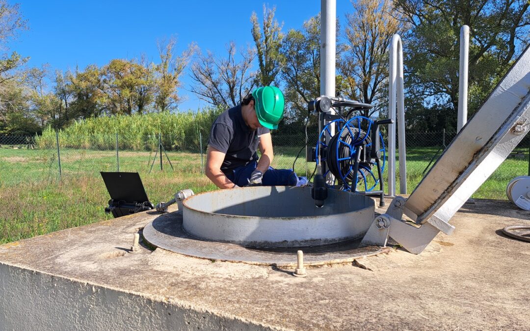
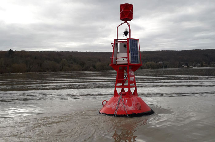
Contents
-
1. The different types of catchment
-
2. Regulations
-
3. Instrumentation of a catchment
-
4. Data acquisition and transmission
-
5. Complex cases
-
6. Costing tool
-
7. Project methodology
1. The different types of catchment
A spring is a place where water naturally emerges from the ground. They can be perennial, i.e. present throughout the year with more or less variation in flow. Others are said to be temporary or intermittent, as they are only present for part of the year, often due to heavy rainfall or melting snow.
Groundwater is always underground, but its position in mountainous areas means that it can be collected by gravity using drains. Like springs, they can be perennial or intermittent.
A catchment is the structure used to extract the water resource. It is a man-made infrastructure that must be adapted to its environment (borehole, pump, gravity-fed, etc.).
1.1 Types of catchment
1.1.1 Springs
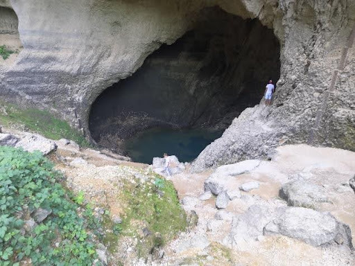
By definition, a spring is the place where water gushes up from the ground. It is then naturally visible in the form of a stream, pond or lake.
1.1.2 Gravity-flow groundwater
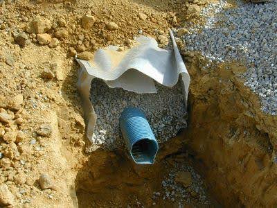
A water table is sometimes close to the natural ground. It is said to be “superficial”. It can be detected by permanently damp or even marshy ground or by a field survey. In this case, drains must be installed to drain the water to a collection chamber. The installation of drains generally involves earthworks, as digging is required to bury them.
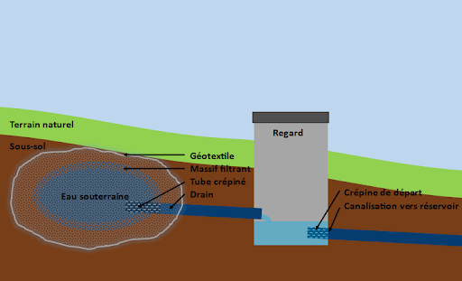
1.2 Types of collection chamber
The presence of a spring or a drained water table will lead to a difference in the way it is captured. There are different types of collection chamber for each type of flow, often determined by their environment and use.
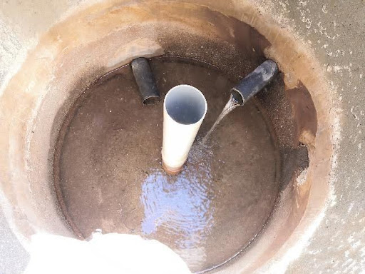
1.2.1 Simple manhole
This is a vertical hole one to several metres deep, cased in concrete and generally round, 80cm to 1m in diameter. Inside is the inlet for the drain or drains, as well as the outlet strainer, and often an overflow for discharge into the natural environment.
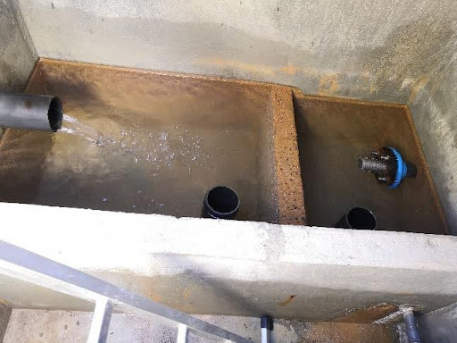
1.2.2 Chamber with sump
In this configuration, the drain or drains converge on a rectangular tank. There may be several tanks in order to break up turbulent flows caused by a large inflow of water. Communication between these tanks is generally by overflow (or free connection then overflow if there are several tanks). The outlet strainer is located in the last tank close to an overflow.
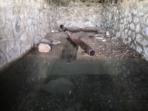
1.2.3 Open channel or tank
These cases occur on springs. The flow takes place in a trough or canal built directly at the point where the water gushes out (e.g. fountain, irrigation canal, etc.). The spring may be channelled over a short distance to its accumulation point.
2. The regulations
The following are the regulations governing the use of a water catchment for drinking water supply to private individuals or local authorities:
2.1 Protection of drinking water catchments
-
La mise en place de périmètre de protection
-
The establishment of extended protection perimeters in the event of increased pollution risk (agricultural origin, etc.)
-
An intruder detection system
2.2 Water analysis
-
The official analysis of the water catchment carried out by the ARS (Agence Régionale de Santé)
2.3 Sampling
-
La DUP (Déclaration d'Utilité Publique)
-
- May impose a limit on instantaneous flow and/or daily volume
- May require discharge into the natural environment
Withdrawal authorization and prefectoral decree
-
| Perimeters | Objectives | Description |
|---|---|---|
| Immediate protection perimeter (PPI) | To prevent accidental pollution and damage to structures. | This corresponds to the area around the wellpoint. The land within it must be enclosed and fully owned by the project owner. Its essential role is to prevent deterioration of the works and avoid spills of polluting substances in the immediate vicinity of the catchment. |
| Close protection perimeter (PPR) | Protecting the catchment from the underground migration of pollutants | This corresponds to the "catchment area" of the water source and is designed to protect the catchment from the underground migration of pollutants. It may be made up of separate parcels. Within this perimeter, all activities likely to cause point-source or accidental pollution are prohibited or subject to special regulations. |
| Perimeter of remote protection (PPE) | Reinforcing protection of the resource | This corresponds to the supply zone of the water catchment point, or even the entire catchment area, and can therefore cover a very variable surface area. It has been created to reinforce general regulations regarding the risk of pollution from certain activities in the area concerned. It allows special regulations to be issued to take account of specific local circumstances. |
3. Instrumentation of a water catchment
3.1 Why instrument a water catchment?
As stated in part 1, a spring or water table may be permanent or temporary. In our case, the catchments used to supply drinking water are, for the most part, perennial, but can experience significant variations in flow over the seasons. What’s more, with increasingly frequent droughts, some of the springs or groundwater used may also dry up.
Monitoring water catchments is part of monitoring the drinking water supply. It is essential to ensure the long-term supply of water to the population. This monitoring is carried out by regularly measuring the flow rate throughout the year, in order to identify seasonal variations and check whether these are normal (linked to the season) or exceptional (outside the seasonal average).
Regular, close monitoring of a water catchment can be complicated by a lack of time, personnel or access to the manhole. Instrumentation of a water catchment is a way of ensuring long-term monitoring of resources, while increasing the accuracy of measurements. There are a wide variety of solutions that can be adapted to each situation. Even when the infrastructure work becomes major, the installation of instrumentation remains a significant asset in monitoring the resource.
3.2 What do I equip?
A spring or an aquifer is made up of the following parts:
- The inlet. One or more, depending on the number of drains. The different inlets can flow into the same tank or into different tanks.
- The outlet. In most cases, this is made up of a screened tube. Some catchments may supply several reservoirs, or even a nearby dwelling directly. In these cases, there will be several outlets.
- The overflow. Here too, there may be one or more overflows, the most important being the one near the outlet strainer.
For simple monitoring, you need to know at least the total flow rate through the catchment. For more detailed monitoring, all three flows need to be measured: inflow, outflow and overflow; the last measurement being the result (sum or difference) of the other two.
In the case of multiple inflows, you can choose to measure them together or separately, depending on the information you want to have (inflow from different sources or several drains). Where there are several overflows, beware of possible losses between the different zones, which may interfere with the measurement.
As far as possible, only one overflow should be kept close to the outlet. The water withdrawn is generally measured at the reservoir using a meter. Be careful, however, to check that there is no overflow to the natural environment at the reservoir.
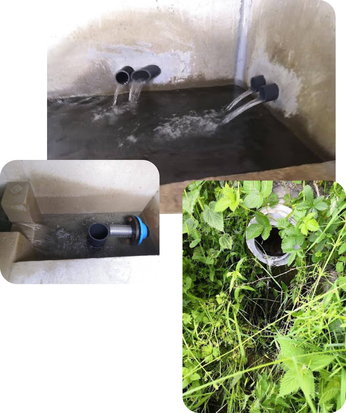
3.3 The layout
In most cases, the flow rate from a spring or gravity-fed water table is measured by circulating the water through a weir or sized channel over which the height of water is measured. A formula is used to convert this height into flow rate. If the water is channelled through pipes, a meter can also be used. We will look at the different systems in detail below.
3.3.1 Weirs
- V-shaped: These are the most common. The standard angles are 28.4°; 53.8°; 90° and 120° depending on the flow rate to be measured (standardisation is based on easy-cut sizes according to the base and height of the triangle). They can be used to measure low to medium flow rates with wide fluctuations.
- Rectangular: A little less common, this weir is used for high flow rates without major fluctuations.
- Trapezoidal: Rarer, this is a combination of the previous two. They are used to measure high flow rates subject to wide variations.
Although it is not always easy to create a box with a weir, it is possible to adapt a box with an integrated weir directly to the inlet pipe.
3.3.2 Channels
Whether Venturi, Parshall, Khafagi or other types, all flumes operate on the same principle. Only their size and shape vary. Their use will therefore depend on the flow rate and the site. They are more often used in open channels because they require space for installation. They also need to be installed with great precision (to the nearest millimetre).
3.4 Instrumentation
3.4.1 Level sensors
The systems described above work in conjunction with a water level sensor to establish the level/flow relationship. All have different measurement ranges and must be adapted to the site. For springs, the lowest ranges (0-1 m or less) will give the best accuracy. There are different types of measurement technology:
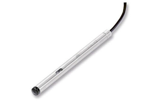
The most widely used sensor. It works by immersion, so it’s easy to install. It measures a variation in pressure using a piezoresistive membrane. It operates in analogue mode and has low power consumption. It is the least expensive sensor (between €400 and €500).
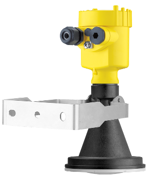
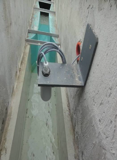
It is positioned above the water level and measures the variation in level from a distance (a few centimetres to several metres). It requires a lot of space and is a little trickier to install. Its power consumption is similar to that of a piezoresistive device. It is more accurate, but slightly more expensive (€500 to €600). There are two types of contactless sensor: radar, which is insensitive to the external environment (variations in temperature, humidity, etc.), and ultra-sound, which is slightly more accurate, but sensitive to the external environment and loses accuracy in turbulent flows.
3.4.2 Meters
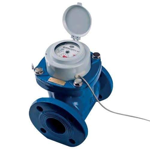
Usually found in distribution systems, this is an inexpensive (€500), low-maintenance solution, but not always easy to install. It must be located on a load pipe, have a transmitter head and be connected to a remote management system capable of converting a volume into a flow rate.
3.4.3 Other solutions
The equipment described above is commonly used. There are other systems which, depending on the installation, may be more practical but less accurate. More anecdotal, they are not to be preferred to other more common and therefore more tried and tested systems. Here are a few examples:
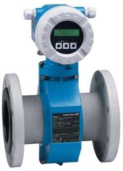
There are several flowmeter technologies (Coriolis effect, ultrasonic, turbine, etc.), each with its own advantages and disadvantages. The most commonly used type of flowmeter is the electromagnetic flowmeter. It’s also the cheapest (€2,500). There are three main disadvantages to installing this equipment in a natural environment. Firstly, it must be used on a pipe under load. This requires special installation of the pipework. The second is that it requires a 230V or lithium battery power supply. This is why this system is used more on tank inlets. Finally, it is susceptible to corrosion and requires maintenance. To be compatible with remote management, it must be fitted with a digital output.
This type of flowmeter can be used on unloaded pipes.
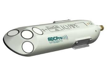
The last system presented is flow measurement using the Doppler effect. This system allows direct measurement by simply positioning the device in the water flow. Apart from its high price, it has two shortcomings when it comes to calculating the flow from a source. Firstly, it is designed for large spaces, in running water, and is therefore reserved for open channels and large pipe diameters (>400mm). Secondly, this technology relies on the presence of suspended matter in the aquatic environment. In most cases, the purity of the source water greatly reduces the accuracy of the device. However, it is worth keeping abreast of developments in this technology.
4.1 PLCs
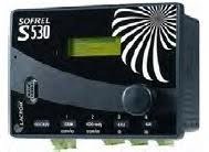
PLCs are the most complete devices. Data can be processed directly before being transmitted, and several different types of sensor can be connected. Their large capacity also makes them more energy-intensive. Even if a battery and a solar panel can meet their electrical needs, it is advisable to use them only with 230V domestic current.
4.2 Stand-alone data loggers
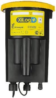
Data loggers with or without communications, commonly known as loggers (or dataloggers), are mini-automata with restricted access. Only a limited number of sensors can be connected, and not all types are accepted (few loggers accept digital probes). Not all models are equal. While some can pre-process the data, others simply send it as is. In our case, it is worth using a datalogger capable of converting water level into flow (or volume into flow).
There are many advantages to dataloggers. Firstly, they are electrically autonomous. Battery-powered, their autonomy ranges from a few months to several years (10 years theoretically, 5 to 6 years in real-life conditions). Another important point is that they are impervious to rain and humidity (not immersion), which makes them easier to install, whereas a PLC would have to be protected by an electrical cabinet. And because they are designed for pure data acquisition, they can store a large amount of data that can be physically retrieved by connecting them to a PC. Many have an internal modem and allow remote transmission, a point to which we attach great importance.
4.3 Networks
Once the data has been acquired, there are two ways of retrieving it. As previously stated, we can retrieve the data manually from the device, but the most interesting solution is of course to automate the sending of remote data. To do this, the remote management system must have a modem and a network connection. There are various networks that can be used:
- GPRS/3G/4G: This is the best known of all, being the network used by mobile phones and smartphones. To use this solution, the datalogger must contain a 3G or 4G modem, a SIM card and an operator subscription. There are multi-operator subscriptions that automatically select the best network (€5/month).
- Satellite: The location of springs in medium and high mountains is not always conducive to the telephone network. In the absence of a mobile network, satellite communication is a good alternative. The subscription is higher (€20 to €30/month) for the same cost of equipment. However, the democratisation of technology is gradually driving down the cost of packages.
- Low-speed networks: The best-known are LoRa Wan and SigFox. Often dependent on traditional telephone networks, they are more effective in urban areas and less present in rural and hilly areas. Their use requires a little more planning, but they enable data to be exchanged where operator networks are too weak. On the other hand, subscriptions are much cheaper (€5 for more than 100 sensors).
Where no network is available for remote transmission, the use of a logger/recorder may be a good idea. This will enable daily data to be acquired, with a visit to the site planned once or twice a year.
4.4 Data recovery
Depending on the method or product used, the data will not be transferred in the same way. It will either be sent directly to the customer server, or via the manufacturer’s platform.
- Direct transmission: In this case, the PLC or datalogger is programmed with the client server’s identifiers and sends the data to a folder on the server (usually via FTP or SFTP protocol). The data can then be processed directly from the files sent.
- Via platform: With this solution, the datalogger manufacturer retrieves the data and makes it available to the customer via a web platform. Depending on the supplier, a file with the data can also be transferred to the customer. The only advantage of this solution is that the data can be viewed on the manufacturer’s web platform, but this comes at a cost and the customer will have to pay a subscription fee for this service. In addition, it is often sufficient to send the data once, as it is then managed by an internal viewing platform or one offered by another service provider.
5. Complex cases
Below, we will look at two special cases, but which correspond to situations we encounter regularly.
5.1 Abstraction and water rights
Water belongs to and benefits the owner of the land. He can therefore use it as he wishes, except if it forms a watercourse (stream, river, etc.) at the end of the plot. If this resource is used by the local authority or a syndicate, they must sign an agreement or contract with the owner of the spring.
If the catchment is owned by the local authority, it is not subject to water rights for the benefit of pocket dwellings. It is up to the manager to intelligently establish sharing rules if he so wishes.
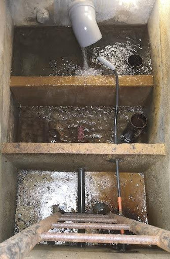
5.2 Submerged or inaccessible structures
Some catchments may be entirely submerged or have hidden inlets or outlets.
In the first case, if it is not possible to lower the overflow, we can try to instrument the inlet of the catchment or its upstream pipework directly. Otherwise, we will have to multiply the measurement points by equipping the outlet (or inlet to the reservoir) and the outlet of the overflow.
The other solution, valid for both cases, is a complete overhaul of the civil engineering. This last solution is of course very expensive (ranging from several thousand euros to tens of thousands of euros), but it is also an opportunity to start again with a healthy catchment that complies with standards and is suitable for instrumentation.
6. Costing tool
Table 2: Summary of costs to help with instrumentation costing
| Element | Description | Price |
|---|---|---|
| Datalogger (with remote management) | Records, converts, stores and sends data. | 1500€ |
| Sensor | Measures water level. | 500€ |
| Threshold | Enables height-flow conversion thanks to a standardised notch. | 500€ |
| Divider plate | Creates an additional tray or raises an existing one. | 1000€ |
| Partition plate with threshold | Creates an additional tray with integrated threshold. | 1500€ |
| Meter | Measures the volume of a pipe under load. | 500€ |
| Flowmeter | Measures the flow on a loaded pipe. | 1500€ |
| Labour (day for one person) | Represents the approximate price for a day's work | 450€ |
| Operator subscription | Represents the monthly telephone subscription. | 5€/mois |
A day’s work is rarely carried out by a single person. It is therefore advisable to double the price of labour to include a second person.
The above prices are based on an average suggested by suppliers. They may vary depending on the manufacturer, technology, precision or material chosen. Labour costs may also vary according to the accessibility of the collector and the difficulty of the work.
7. Project methodology
Table 3: Gant chart for project time management
| Action | Description | Duration (working days) |
|---|---|---|
| Formalising the solution | Creation of the catchment sheet. | Half a day to create the data sheet and consider the instrumentation solution(s). |
| In-depth visit | Second visit for verification and final choice of equipment and solution. | Same as first visit. |
| Diagnosis | Linked to the second visit, a camera visit to check the condition of the drains if necessary. | Allow an extra half-day in addition to the visit. |
| Final costing | Exact costing of work and materials. | Allow a week for all supplier quotes to be collated. |
| Order | Order material with delivery time. | Longest lead time. Some suppliers take up to 6 weeks. |
| Works | Work carried out on site. | One to two days for a simple case. One week to one month if civil engineering work. |
| Validation | Verification of work and receipt of data. | Allow one to two days for data to be sent for checking. |
This methodology does not take into account all the administrative procedures that are useful for the deployment of the project, but which are tedious and rarely reducible.
The length of time taken to prepare the project varies according to the workload of the company responsible for the works. Note that in some cases, the site may not be accessible all year round (snow, mud, etc.). An assignment schedule should always be drawn up in advance with the company responsible for the work.
For the “diagnostic” part, the intervention of a specialist company may be required if the installer is unable to carry out the camera inspection. Video inspection of a drain is more complex than for a borehole (broken drain, filled drain, source in karstic networks, etc.).
8. Examples of projects
9. List of partners
Installing the instrumentation is extremely important. It is the key to measurement accuracy. It is therefore important to work with a competent and reliable company. imaGeau has compiled a list of partners with whom it has already worked and which it recommends.
HydrauDiag
34080 Montpellier
Tel: 06 11 10 55 24
Email: f.pillet@hydraudiag.com
HydroServices
36, rue du Cerf
67350 UBERACH
Website: https: //www.hydroservices.net/
Phone: 03 88 07 50 06
Fax : 03 88 07 50 09
Email : accueil@hydroservices.net

Ceneau
265 Avenue de l’Industrie
34 820 TEYRAN – France
Website: https: //ceneau.com/
Phone : +33(0)4.67.04.16.43
Fax : +33(0)4.67.52.08.55

Tetraedre France
1 impasse des Puyots
65310 ODOS – France
Website: https: //www.tetraedre.com/
Tel : 06 80 16 14 45
Email: fabien.levard@tetraedre.com

Saur
Operators such as Saur have dedicated teams capable of carrying out instrumentation and civil engineering work. Here is a list of contacts by region:
| Region | Contact | Contact details |
|---|---|---|
| PACA | Anthony GAYRAL | anthony.gayral@saur.com 04 94 01 37 90 06 50 86 88 27 |
| Auvergne Rhône | Hervé TOURNIAIRE | herve.tourniaire@saur.com 04 75 00 12 23 06 80 48 83 06 |
| Rhin Bourgogne Loire | Océane THOMAZEAU | oceane.thomazeau@saur.com 07 60 58 62 85 |
| Hauts-de-France | Anne-Claire LELEU | anne-claire.leleu@saur.com 03 64 47 93 53 |
| Languedoc-Rousillon | Vincent GAUZE (34, 11, 66) | vincent.gauze@saur.com 04 67 66 52 34 07 61 31 27 52 |
| Languedoc-Rousillon | Jean-Christophe GLOUTON (30, 48) | jean-christophe.glouton@saur.com 04 66 68 72 83 06 76 72 33 13 |
| Atlantique | Jean-Jacque LABROUSSE | jean-jacques.labrousse@saur.com 05 46 51 37 10 06 65 51 08 73 |
| Bretagne | Eric DUVEAU | eric.duveau@saur.com 02 99 52 08 79 06 87 86 30 74 |
| Limousin | Laurent PUGNET | laurent.pugnet@saur.com 05 55 17 31 34 07 62 48 70 98 |
| Pyrénées Garonne | Vincent SAVIGNAC | vincent.savignac@saur.com 02 96 85 64 15 06 74 94 74 26 |
The company below is not an installer, but offers complete satellite communication solutions (intelligent logger + data transmission).

HioTee
Cap Alpha – 3 avenue de l’Europe
34830 Clapiers
Website: https://www.hiotee.com/
Email: contact@hiotee.com
References
Type of sources :
- http://id.eaufrance.fr/nsa/918
- https://www.memoireonline.com/10/13/7528/m_Les-eaux-souterraines-captage-exploitation-et-gestion12.html
Thresholds :
Regulations :
